This page explains everything you need to know about irrigation valves!
There are many different kinds of irrigation valves available. You will need at least two different types for your irrigation system.
1. Emergency shut-off valve:
This valve should be installed at the closest point possible to your water source, that is, the location where you tap in for the irrigation system. Without this valve you will need to shut-off the water to the entire house when you want to work on the mainline or irrigation valves. The most commonly used valves for this purpose are “gate valves”because they are inexpensive. Unfortunately the cheap gate valves you’re likely to find in your local hardware store also tend to fail after a very short period of time. I recommend that you use a “ball valve”, or if you need a really big shut off valve (over 3 inch size) use a “disk valve”, or “butterfly valve”. These cost a bit more but are much more reliable and will last several times longer. So if you pay twice as much for a ball valve it’s probably still the best deal! If you want to use a gate valve make sure that it is a “wedge” type and buy a good quality one (it will probably cost more than a ball valve.) There’s nothing worse than trying to repair a system when you can’t shut off the water completely. OK, that’s about all you need to know about emergency shut-off valves. The rest of this page is about Irrigation Control Valves.
2. Irrigation Control Valves:
These are the valves that turn on and off the sprinklers, they also may be used for drip irrigation systems. Other names sometime used for them are irrigation valve,sprinkler valve, solenoid valve, and lawn valve. Sometimes they are incorrectly called Garden Valves. A garden valve is a manual valve that you connect a garden hose to.
Globe Valves vs. Anti-Siphon Valves
You have two basic styles of control valves to choose from.
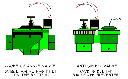
Globe or angle valve:
This valve is available in any size and is commonly installed underground in a box or vault. Since it doesn’t incorporate a backflow preventer you must provide one separately. See the article on backflow preventers. The globe style valve is the most commonly used valve on commercial and larger size sprinkler systems.
Anti-siphon valve:
Available only in 3/4″ and 1″ size. This is the most common used valve style for homeowners. The anti-siphon valve incorporates a backflow preventer into the valve. This saves a considerable amount of money, as backflow preventers are very expensive. The anti-siphon valve MUST be installed above ground and MUST be at least 6″ higher than the highest sprinkler head. This means that if you want to use anti-siphon valves you will have to locate the valves at the highest point in your yard, and run a water supply pipe to them from the water source (this water supply is called a “mainline”). The mainline pipe leading to the anti-siphon valves should be buried 18″ deep to protect it.
Valve Operation/Control Systems
Manual, Hydraulic and Solenoid Valves:
The sprinkler valves may be manually operated or they can be remotely controlled (automatic valves.) Manual control is simple, the valve has a handle that you use to turn it on and off using your hand as the power source. Remote control valves are either electric or hydraulic operated using a timer or other signaling device to tell them to open and close. Today almost all of sprinkler control valves are electric powered solenoid valves. The electric solenoid valve operates on 24 volt alternating current (vac) and is turned on and off by a timer called an “irrigation controller” or often just “controller”. Anti-siphon, globe, and angle valves styles are all available as automatic valves.
Solenoid Valve and Controller Compatibility
Pretty much all 24volt valves and controllers are compatible with each other. The most common exception to this rule is valves operated by controllers that are battery or solar powered. (By battery powered I mean they are not plugged into a power source other than the battery. Many controllers have a battery to prevent program loss in case of a power failure, these are not “battery operated”.) So in most cases you can buy a brand “X” controller and it will work fine with brand “Y” valves. You can even mix two or more brands of valves together if for some reason that appealed to you. For example the irrigation system where I test valves and controllers has many different brands all running together. If the valve is not “universal” or compatible it will typically have a warning on the packaging.
Flow Control
I strongly recommend that if you are going to use automatic valves, you select a valve model that has a manual flow adjustment control feature on it. Don’t confuse the flow control with a manual on/off switch. The flow control is a separate handle (sometimes a screw) in addition to the manual on/off control on the valve. This flow control feature is not found on many of the less expensive “budget” valves. The flow control bypasses the automatic valve features allowing the valve to be closed in an emergency by turning a handle just like a standard manual valve. More important is that it also allows the valve to be “throttled”, that is, the water flow may be adjusted to any rate desired. This ability to adjust the flow rate is very useful in many different situations, both when installing your sprinkler system and later when managing it. It can literally make the difference between being able to make a troublesome valve work and having to remove and replace it! I very strongly suggest that this is a feature worth the extra cost.
- Using the manual flow control you can manually force the valve closed if it sticks open. The manual on/off switch will not close the valve if it is stuck open. Failure to close automatically is one of the most common valve problems, so there’s a good chance that someday you will use the flow control to force closed a valve that is stuck open.
- If your flows are on the low end of the valve’s operation range, it may be helpful to throttle down the flow control to make the valve close faster and more reliably. Without the flow control feature you may have a lot of problems in this situation, you will probably have to replace the valve.
- Partially closing the flow control will make the valve close faster, which is not something you want to do normally, but sometimes it is desirable. On automatic systems it is common for the next valve to open before the previous one fully closes. The resulting loss of pressure due to two valve circuits being on at the same time can cause the first valve to never fully close. A flow control on the valve can help correct this problem.
- Buy valves with the flow control feature. Just do it. Don’t be one of the many people who later makes some lame excuse to me, like “the guy at the store, who normally works in the paint department but was filling in for the day on the irrigation aisle, said it was a waste of money!”
Should You Use Metal or Plastic Valves?
Sprinkler valves come in both brass and plastic models. Most valves used today are plastic, but brass is not out of the picture. There is no doubt that a brass valve will last longer in most situations, especially if installed above ground in the sunlight. From an operational point of view both are reliable, especially for automatic systems. For manual valves my experience is that plastic valves wear out fast and have a very short life. Brass will last much longer. If you use plastic valves above ground you may wish to consider building a cover for them to protect them from sunlight, which can destroy the plastic over time.
Two types of plastic material are used for valves. Glass-reinforced nylon is the best, it is tougher, more resistant to impact, and has a higher pressure rating. PVC is used for lower cost valves, it still is pretty strong, although that really depends on how thick the plastic is! A few valves use ABS plastic or polyethylene, especially for minor parts like screws or caps. Both of these plastics are less strong and are typically used for parts with little stress on them. I recommend avoiding valves with “solvent weld” connections (the pipe glues directly into the valve.) If the valve fails, they can be difficult to replace. Only the cheapest valves come with solvent weld connections. Hmmm… cheap valves fail more and with glued ends are harder to replace- sounds like a bad idea.
Jar Top or Traditional Top Held on with Screws?
OK, just personal opinion here, but I don’t see any advantage to a jar top valve. Yes, they seem to work as well as a top with screws holding it on. They primarily are only found on cheaper valves. The only selling point I have heard for them is that they are supposed to be faster to open for repairs. Are you repairing it that often? I hope not! But I guess if it is a cheap valve…? My experience is that by the time the valve is old enough to need repairs the jar top has seized up and it takes a strap wrench to get the top off. Personally I prefer using a simple screwdriver to remove a few screws as opposed to wrestling with a strap wrench in a tight spot like a valve box.
Maintenance
Today’s valves are pretty maintenance free. Almost all automatic valve failures result from installation or design problems. Ignore the following and you will hate your valves regardless of what type or brand you buy!
Join the “Hall of Regrets”! Simply ignore the following advice, then send me your “I’m an idiot, I wish I’d listened…” sob story. I’ll add it to my collection and shed an alligator tear or two for you!
- Dirt in the irrigation pipes. Inside the valve there are very small water passages that lead to and from the solenoid. Water must flow freely through these small passages. If a grain of sand or glob of algae gets into these passages it can block them and the valve will fail to open or (more likely) fail to close. It is critical to flush all the dirt out of the pipes before installing the valves. A 100 to 200 mesh filter installed at the water source connection can also help keep out contaminates that comes in with the water supply. You may be surprised to learn that most water companies have considerable amounts of sand in their pipes. When you install a new sprinkler system the higher flows stir up this sand and then it gets into your new system. That’s why I suggest to you in the installation tutorial to flush for so long. You have to get the sand out of both the sprinkler system pipes and the water supply pipes! I can’t stress this enough! It’s like a cheap low-flow toilet. You have to flush, flush, and flush again!
- Almost all valve solenoid failures are caused by water getting into the solenoid. The water gets into them through the wires. The solenoid wires have multiple strands of wires twisted together with insulation around them. Because they are twisted there are very small gaps between the wires which form passages along the length of the wire. Water is sucked up through these small passages and deposited into the solenoid by capillary action. Thus it is critically important that the wire splices on the valves be completely water proof so that water can’t be sucked into the solenoid through the wires. You should water-proof the wire splices right after you test the valves! No kidding, a single drop of water on the bare valve wire end can be quickly sucked up into the solenoid and will ruin the solenoid. The Installation Tutorial has more on this.
Valve Size and Pressure Losses:
Emergency Shut-Off Valve:
The pressure loss through the emergency shut-off valve is not significant enough to worry with. We will ignore it. The emergency shut-off valve should be the same size as the pipe it is installed on. If a smaller size shut-off valve is used then you do need to worry about losing pressure through the valve. Probably about 2 PSI would be a safe assumption of the pressure loss.
Automatic Valves:
WARNING!!! If you use the wrong size automatic valve, the valve may not work! READ THAT AGAIN! Let it sink in. The correct valve size often will not be the same size as the pipe it is connected to.
The pressure loss in an automatic solenoid valve is the primary energy source used by the valve to open and close the valve. The electricity sent to the valve solenoid is just used to jump-start the process, the real force used is the water pressure. If the valve doesn’t have enough pressure loss it will not have the energy needed to close by itself. Always size automatic valves based on the flow rate using the manufacturer’s chart as a guide. Never assume that the valve should be the same size as the pipe! It is very common for the valve to be a different size than the pipe it is installed on. I have seen some rare cases where a 3/4″ valve was the proper size for the flow through a 2″ pipe!!! If you absolutely must guess, use the next solenoid valve size smaller than the pipe size and assume a pressure loss of 6 PSI. Never guess if your flow is less than 5 GPM, always use a chart! Many automatic valves won’t work at all at flows below 5 GPM!
The size of the automatic valves is determined by the manufacturer’s recommended flow range, together with the pressure loss through the valve at the selected flow. You will need to get the valve manufacturer’s flow chart for the model of valve you plan to use. This information should be on the valve packaging. If you can’t find it on the package, try the valve manufacturer’s website or ask for a data sheet on the valve at the store where you buy the valve. (At discount home improvement stores you are likely to get a blank stare from the employee if you ask for a data sheet!)
Some valves don’t appear to have data sheets available anywhere, so as a last resort I’ve assembled some data for you based on my own research for some of the more popular ones. You will find it in the reviews on this website, Click Here. That said, if the valve manufacturer doesn’t provide this necessary information it shows an extreme lack of professionalism, I would be very reluctant to use the product!
If you can’t find pressure loss and flow range information for the valve you want to use, I strongly suggest you use a different brand of valve. After the valve is installed is not a good time to discover it’s the wrong size and won’t open or close automatically!
Example: let’s say you are going to use an automatic anti-siphon type valve. Your Design Flow is 20 GPM, so for now we will assume the flow through the valve will also be 20 GPM. (If it turns out the flow will be less,you can resize the valve later.) The manufacturer’s flow chart would look something like this:
Doesn’t Work Valve Company, Inc. – Valve Performance Data
| 5 GPM | 10 GPM | 15 GPM | 20 GPM | 25 GPM | |
| 3/4″ Anti-Siphon Valve | 5.0 PSI | 5.5 PSI | 6.0 PSI | 8.0 PSI | — |
| 1″ Anti-Siphon Valve | 2.5 PSI | 3.5 PSI | 3.0 PSI | 4.0 PSI | 9.0 PSI |
Warning: The chart above is not real. DO NOT USE THESE VALUES!
The example chart above tells us that the pressure loss for our valve at 20 GPM flow would be 8.0 PSI if we used a 3/4″ valve and 4.0 if we used a 1″ valve. So we could use either one. The pressure loss information from the chart would be the number that you write into your Pressure Loss Table on the “_____ PSI – Valves” line. So if we decided to use the 3/4″ valve, the value would be 8 PSI. But what if after adding all the pressure losses in the loss table, you discover that the losses are too high? In that case you could go back and change to a 1″ valve. That would reduce the pressure loss down to 4 PSI, rather than 8. With that said, as a general rule I try to avoid losing more than 6 PSI through a valve. So I would not use a 3/4″ valve in the example above if it were my sprinkler system. Why? Valves need pressure drop for them to work correctly, but really high pressure losses are hard on the valve. As the pressure loss through an automatic valve increases, the speed that the valve closes also increases. Thus a high pressure loss can cause the valve to snap closed extremely fast, and that is bad for the entire sprinkler system. Plus the water is moving extremely fast through the valves at those higher pressure loss rates, resulting in more wear on the valve seats. So the valve will fail earlier.
If you looked closely at the chart above you may have noted a couple of interesting items. First, and most obvious, is that no pressure loss is given for a 3/4″ valve at 25 GPM. This is because that flow is outside the acceptable range for the valve. You should not use the valve for that flow. The next item is less obvious, but if you look closely, you will notice the pressure loss for the 1″ size valve is less at the 15 GPM than it is at the lower 10 GPM flow! No, it isn’t a mistake. It is very common for valves to have higher pressure losses at very low flows, so if you notice this on a flow chart; don’t panic, it’s not a misprint.
Can a valve be smaller than the pipe it is connected to?
As you move through the tutorial you will find that even though the valve will handle a certain flow, that flow is often too high for the same size of pipe. So it is very common to have a valve that is one, or even two, sizes smaller than the pipe it is installed in. In fact it is so common that they actually make special pipe fittings (connectors) for this. For example they make a PVC plastic male adapter that glues onto 1″ pvc pipe, but has 3/4″ threads to allow you to install a 3/4″ valve on a 1″ PVC pipe. They also make one that glues onto 1 1/4″ pipe but has 1″ threads.
For Manual Valves:
Manual valves are much more forgiving than automatic valves. You don’t need to worry about having enough pressure to allow the valve to close by itself, it uses “elbow grease” to power it! However, you still need to find out what the pressure loss through the valve will be so you can enter it in your Pressure Loss Table. As with the automatic valves, you use a chart provided by the manufacturer for this. Follow the same procedure given above for automatic valves. Unfortunately, pressure loss data for manual valves can be hard to find as many manufacturers don’t provide it. As a general rule, allow 2 PSI pressure loss for a globe or angle type manual control valve, 5 PSI if it is an anti-siphon valve. Manual irrigation control valves should be of the “angle” or “globe” type with replaceable rubber seats. Never use a gate valve as a control valve. Gate valves are not made to be regularly opened and shut. Many gate valves will start leaking after as little as 10 uses!
Want to use a manual valve now but change to an automatic valve later? No problem. Simply design for the automatic valve, but use the manual one instead. Then you can replace it later when you want to automate the system. Another way to do this is to install the automatic valve and simply operate it manually using the manual on/off lever. If you do this, then later you just install a controller as well as wires between the controller and the valves and you have an automatic control system.